Prev
:: Top ::
Next Prev
:: Top ::
Next
|
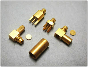
| Broadband performance with low reflection DC to 6 GHz, providing a high-quality solution at a low cost |
| Quick connect/disconnect snap-on mating reduces installation time |
| Available in straight and right angle plugs and printed circuit board connectors |
| Antennas |
Telecom |
Base Stations |
Cable Assemblies |
| Radio Boards |
Components |
Instrumentation |
Radar |
| GPS |
|
|
|
| Impedance |
50 Ω |
| Frequency Range |
DC - 6 GHz |
| Dielectric working voltage @ sea level |
170 V rms, 50 Hz |
| Dielectric withstanding voltage @ sea level |
500 V rms, 50 Hz |
| VSWR |
SMT & Edgecard: Cabled
DC - 4 GHz: 1.15 max ; Straight semi-rigid: 1.15 max
4 - 6 GHz: 1.40 max; Straight flex: 1.20 max, R/A semi-rigid: 1.20 max, R/A flex: 1.25 max |
| Contact Resistance |
10 mΩ |
| Insulation Resistance |
500 MΩ |
| Outer Contact Resistance |
5 mΩ |
| RF Leakage |
-60 dB minimum @ 3 GHz |
| Engagement force |
3.4 lbs |
| Disengagement Force |
1.4 lbs to 3.4 lbs |
| Contact Captivation |
2.3 lbs |
| Durability |
500 cycles |
| Leads |
Beryllium copper with gold plating per QQ-C-530 |
| Contact Socket |
Beryllium copper with gold plating per QQ-C-530 |
| Outer Conductor |
Beryllium copper with gold plating per QQ-C-530 |
| Housing (SMT) |
Liquid crystal polymer |
| Insulators |
TFE, Delrin |
| Clamp Gaskets |
PTFE per ASTM-D1457 |
| Temperature Range |
-40° C - + 90° C |
| Temperature Shock |
MIL-STD-202, method B |
| Humidity |
MIL-STD-202, method 103, test condition B |
| Vibration |
3 cycles, 3 opposite directions, 10-150 Hz, 10-60 Hz: 0.75 mm/.030 in., 60-150 Hz 10 G's |
| Mechanical Shock |
MIL-STD-202, method 213, test condition B |
Note: These characteristics are typical but may not apply to all connectors.